Thursday, March 29, 2012

Adventures in paradise: redux

Remember this post?  I'll wait while you go review it.

Go ahead.

It's been a little less than two years since I wrote it.  And you know what?  Dreams really do come true...
  • Carol and Livia aboard s/v Estrellita are right now in mid-pacific, on their way to from Mexico to the Marquesas.  They are doing well, and are having the time of their lives.
  • Mike and Rebecca aboard s/v Zero to Cruising are island hopping their way thru the Caribbean, enjoying white sand beaches, coconut palms, and hiking thru tropical forests.  They too are having the time of their lives.
Dreams do come true.  Tho it must be said that they come true most often for those who work to make them come true, as both these couples did.

What are you dreaming?

What are you doing to work toward those dreams?
Share/Bookmark

Wednesday, March 28, 2012

Hope

The character of the rain changed last nite.

Those of us in Seattle are exquisitely tuned to the slightest changes in our rain, which we call "weather".  And last nite it was different.

Instead of the wind-driven rain which almost hurts when it hits you in the face, and the howling in the rigging which that same wind causes, last nite it was calm.  And the rain fell quietly, gently.  It's the kind of rain that you can imagine the daffodils welcome, with their blossoms tilted skyward.

Surely spring is coming
Share/Bookmark

Monday, March 26, 2012

Project ST5000: Step by step

Disclaimer
Performing these tasks is fraught with opportunities to destroy the ST5000 autopilot, the Benmar drive unit, or both.  Take nothing here as directions on how to modify the Benmar drive to be controlled by the ST5000 - instead, this is a guide to understanding what I did with my drive unit. Your drive unit may be different.


Finally, if you are not comfortable with electricity and electronics, do not attempt this conversion.  You must be able to understand fully what needs to be done and you must take full responsibility for making the changes necessary on your drive. 


I accept no liability for your failure to successfully convert a drive because:
  • These directions may be faulty.
  • Drive units may vary
  • Your skill level may not be up to the task
  • Your understanding may be incomplete
all of which can lead to failure and destruction of the ST5000, the drive unit, or both.

I know that what follows fails as a recipe for making the conversion.  Actually that is on purpose.  If someone were to blindly follow a recipe, it would almost certainly lead to an expensive failure. 


That said, join me on my journey to understand the ST5000, the Benmar drive, and learn what I did to convert my Benmar autopilot drive unit to make it compatible with my ST5000:
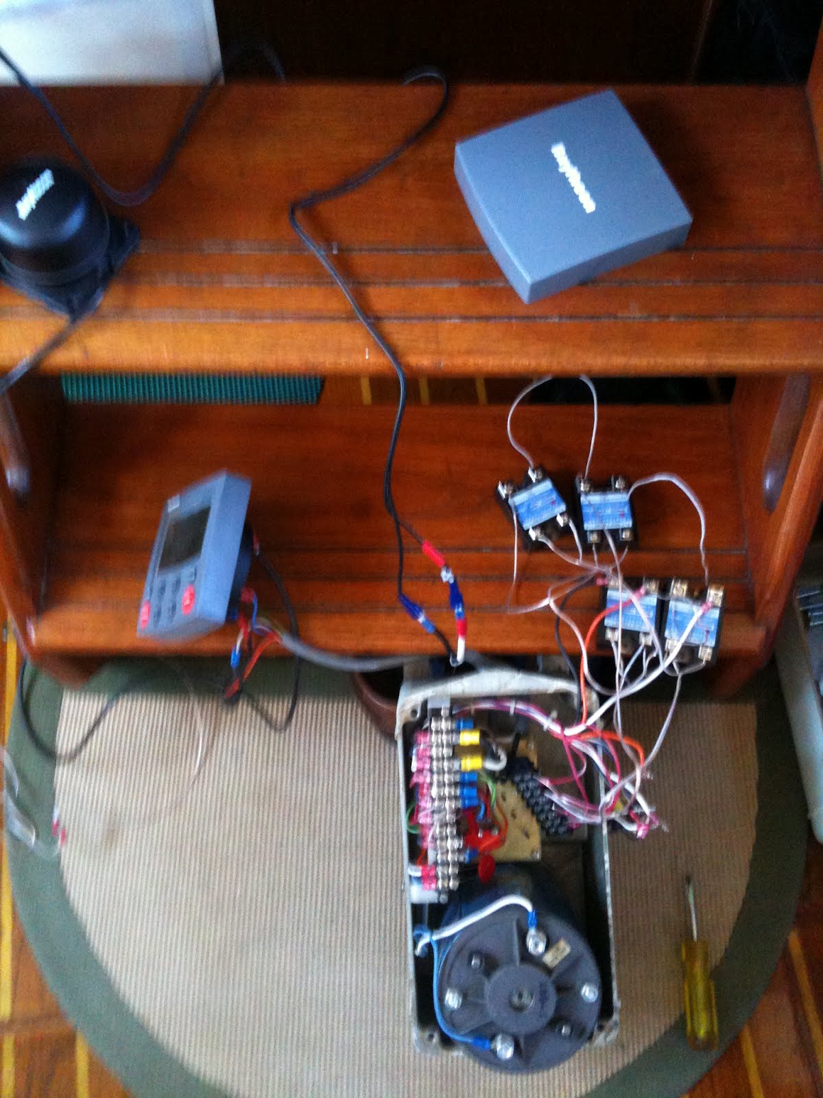
  1. Remove the cover from the drive unit.  This is on the opposite end from the drive sprocket.
  2. Remove the two screws that hold the aluminum plate containing the two large and one small relays from the case, freeing the plate and its relays from the case.  
  3. The two large relays control the drive motor, and the smaller relay controls the clutch.  We will not disturb the clutch relay at this point.
  4. Locate the two heavy orange wires coming out of the wiring bundle and disconnect them from the relays.  These wires each connect to one side of the motor.
  5. Locate the two thin red wires coming out of the wiring bundle and disconnect them from the relays.  These come from the limit switches, and are one side of the relay control wires.
  6. Locate the two thin red wires with white stripes coming out of the wiring bundle and disconnect them from the relays.  These are duplicates for the other side of the relay control wires.
  7. Locate the two heavy white wires coming out of the wiring bundle and disconnect them from the relays.  These are the DC +  feed.  On one of the relays, you will also find a thin white wire under the same screw as the heavy white wire.  Remove it too.  You will also find that there are a white and a black wire going to the relays from a capacitor (silver cylinder) bolted to the aluminum plate.  You may ignore these for the moment.
  8. Locate the two heavy black wires coming out of the wiring bundle and disconnect them from the relays.  These are the DC - feed.  On one of the relays, you will also find a thin black wire under the same screw as the heavy black wire.  Remove it too.  
  9. You should now find that the wire bundle is free, except for the two wires going to the capacitor, and the blue and white/blue stripe wires going to the clutch relay.
  10. Clip the nylon wire ties holding the bundle together and unthread the wires you have loosened.  You will find that they fall nicely into two groups - one long and one short, each for the particular relay that they had been attached to.  You will also find that you have freed a white and black wire pair going to the clutch relay.
  11. Looking at the underside of the aluminum plate, remove the single screw holding the clutch relay to the plate.  This should now allow the plate and the still-attached old motor relays to be removed completely.  Find a longer 6-32 screw and attach the clutch relay to the case thru one of the holes that used to hold the aluminum  relay plate - the hole furthest from the corner of the case is the preferable mount point.
  12. Tho it might seem most convenient, we cannot simply attach the new SSR's to the aluminum plate in place of the old mechanical relays.  The plate is not an adequate heat sink.  We are going to use the cast aluminum case cover as the heat sink.
Now, a little rearrangement of the wiring on the big terminal block in the drive. The purpose of these changes is to reverse the connections to the limit switches so that the common wire is connected to one of the incoming control lines, and the individual switched connections will go to the diode-controlled control lines. The numbering is done counting from the end closest to the motor.
  1. Locate terminal 8.  The incoming red wire will be attached here.  On the other side of terminal 8, you will see a red/white stripe wire - relocate this wire to terminal 9, under the same screw as the red/white wire already on terminal 9.  Now the incoming green control wire is connected to both red/white wires.
  2. Look at terminal 4.  You will find an orange wire - relocate this to terminal 8.  This connects the incoming red wire to the limit switch common connection.  
  3. Install an MOV across terminals 1 & 2.  This puts it directly across the motor terminals.
After these changes, the incoming green control wire is connected to both the red/white stripe control wires, and the incoming red wire is connected to the two red control wires, via the limit switches.  The idea is that if a limit switch is tripped, the control signal for that rotation direction is interrupted, but the signal for the opposite rotation direction is unaffected, allowing the drive to be rotated away from an at-limit condition.
    I installed an MOV across terminals 4 & 7 of the big terminal block - this puts the MOV across the coil of the clutch relay, protecting the ST5000 from inductive kicks from this coil.

    Purchase an 8-terminal terminal strip - this will be used to insert the diodes in the 2 pairs of control wires.  Pay very close attention to the diode polarity in the schematic - if they are reversed, the SSR's could fail to actuate, or incorrectly actuate creating a dead short across the 12V power, leading to at least the destruction of the SSR's.

    Mount the SSR's to the inside of the case cover.  Be sure that the mounting locations will not interfere with anything inside the drive unit when the cover is installed.  Apply silicone to the aluminum plates on the back of the relays before screwing them in place to insure a sound thermal connection to the case.

    Make the control connections on the relays from the new terminal strip containing the diodes, and make the inter-relay connections on the control lines.

    At this point, before supplying the 12V power to the output terminals on the SSR's, I made a lash-up and actually powered up the ST5000 connected to the drive unit.  I verified that when the ST5000 called for rotation, the opposite corners of the H-bridge were activated (the SSR's have LED's that lite when they are actuated).

    Having confirmed my control wiring, I then made the motor and 12VDC connections to the SSR's output terminals.  Connect the white and black wires from the clutch relay to any convenient white and black wires at the SSR's.  I then used the ST5000 to actually turn the motor.  I did this as a final check to confirm that I had things right, and to ensure that I did not have the wiring to the limit switches reversed.  I didn't, but it was a 50-50 chance.  If I had, then the limit switches would have failed to prevent over-rotation, and it would not have been possible to run the drive unit in the reverse direction to clear the over-rotation condition.  If this had happened, I would have simply reversed the connections of the two red control wires coming from the new terminal strip.

    Hookups at the ST5000:  Everything I did presumed the re-use of the existing wire bundle going from the Benmar drive to the Benmar controller in the cockpit.  Here is where the wires in the bundle at the cockpit need to connect to the ST5000:
    • White:  ST5000 DC + 12V power connection.  Since the ST5000 is a delicate instrument, and is now used only to deliver control-level signals, it will draw very little current.  I installed a 0.5 amp fast-blow fuse in the +12V power lead.
    • Black:  ST5000 DC - 12V power connection
    • Blue:  ST5000 + clutch connection.  No negative clutch connection is required.
    • Red and Green:  ST5000 drive connections.  Don't worry about which goes where - if the sense of the drive is wrong (it rotates the wrong way), just reverse these connections.  The ST5000 also has a software switch for this.
      Of course the compass and the rudder reference transducers will also need to be connected to the ST5000, but these are standard connections, done according to the factory manual.

      Share/Bookmark

      Wednesday, March 21, 2012

      Which end of the dock?

      When you live on a boat, One of the constants in your life is the dock, and where along it your boat is tied up.  You may have some choice initially, and as time goes on you will be presented with opportunities to change your slip.  So where along the dock would you like to be?

      Tho I have written about this before, our currently nasty weather recently has got me thinking about one aspect of the choice: the inshore end of the dock vs. the offshore end (on G Dock, they're roughly 1000 feet apart).  Full disclosure:  Eolian is at the far offshore end of G Dock...

      Pros for being at the inshore end:
      • The walk from the car to the boat is short!  This is important all year long because you are constantly moving things (groceries, laundry, ...) to and from the boat.  But it is especially important in the winter because even the walk from the car to the dock head seems interminable in the wind, blowing rain, and snow. 
      • The inshore end of the dock experiences substantially less wind than the offshore end, which is, after all, umm, offshore.
      • From the inshore end of the dock, you can relatively easily chat with folks up on the promenade on shore - this is very handy for when visitors arrive!
      • On G Dock anyway, the inshore end of the dock is a power boat haven - if this is your type of boat, then this is where you probably want to be.

      Pros for being at the offshore end
      • You get to see everybody.  When walking down the full length of the dock, you pass by all the boats, and often have a brief "Hi!  How's it going?" conversation with a lot of folks.  In the summertime, when everyone is outside, anyway. 
      • We have a virtually unobstructed view of the sunsets, and at higher tides, the Sound out at the offshore end of the dock.
      • Out at the offshore end of the dock, things are a lot quieter - the traffic on the street and the RR tracks are 1000 feet further away.
      • On G Dock anyway, the offshore end of the dock is a sail boat haven - if this is your type of boat, then this is where you probably want to be.
      (In keeping with my objective of keeping this a positive blog, everything above is expressed as a "Pro"... I'll leave it to the pessimists to work out the implied "Cons")

        Share/Bookmark

        Monday, March 19, 2012

        Project ST5000: The end of haywire and lash-ups

        Since the lash-up tests were successful, I have moved ahead.

        Relays permanently mounted
        First, I have mounted the relays in their final position, inside the cast aluminum case cover.  Before mounting, each relay got a dab of silicone on its aluminum back plate to ensure good thermal contact with the drive case.  You can see 4 holes on the end where I originally had two relays mounted - this location did not work out because one of the relays interfered with the main terminal strip in the drive.  For ease in wiring, and because I am visual sort of guy, the relays are physically arranged as they are in the schematic - makes for fewer wiring errors on my part.  In this picture, I have completed the inter-relay wiring.

        All hooked up
        Now that the relays are permanently mounted to the cover, it is time to do the real hookup.  Here you can clearly see the additional 8-terminal terminal strip that is used to insert the diodes in the control lines coming from the H-bridge.  (I think some of those leads are going to be too long, and the wire routing could be better.  Some zip ties are called for as well.)  When I do this in our installed unit, I'll drill a couple of holes in the case for screws to mount the terminal strip.  I plan to just trade the case covers.

        Finally, here's the detailed schematic (as always, click on the picture for a full-sized version):
        I am a little nervous with the inductive kick protection/dynamic braking diodes installed across the output terminals of the relays.  The ones I have used are rated at 1 amp, which seems light.  But they haven't blown yet...

        A little later, I will publish a step-by-step guide to the minor modifications to the drive wiring that are needed to make this work.

        Next steps... take a deep breath and modify the installed drive unit, and then do sea trials.  For this to be effective, I need to at least install the compass temporarily somewhere, and I really need to install the rudder reference transducer.  And pull a lot of wire in difficult places.  It's a big commitment.

        The next step is a big one.

        Share/Bookmark

        Wednesday, March 14, 2012

        The things we eat

        Now seriously, how did we get to some of the things we eat?

        As an example, consider coffee:
        1. You pick the fruit
        2. You extract the seeds, and then throw away the fruit 
        3. You dry the seeds, and then burn them in a fire  (what?)
        4. You grind up the burnt seeds and pour boiling water on them (why would you do that?)
        5. You throw away the seeds, and then you DRINK THE WATER!
        The only one of those steps that makes any sense is the first one. And all the intermediate products are noxious – no one would want to consume any of them – you have to go all the way thru the process to get something worthwhile.

        How did humans ever figure this out?


        Inspired by a recent post by our friends on ZTC down in the Caribbean, on cocoa, whose preparation is almost as weird.
        Share/Bookmark

        Monday, March 12, 2012

        Project ST5000: It's alive!

        The lashup
        It works!  I can control the drive from the ST5000+!  Here's the lashup I have been using to test this.

        I have commandeered the wiring that would normally go to the old Benmar controller in the cockpit to carry the power to the ST5000, and to carry clutch actuation and drive signals from the ST5000 back to the drive, using the same wires that carried those functions with the Benmar controller.   It's that fat grey wire going to the ST5000.  By doing so, I eliminate the need to run a new wire.

        I have to have the compass hooked up in order to get the ST5000 to run; that's it on the step above the ST5000.  But I do not have the rudder sensor hooked up, so the autopilot will eventually alarm that it cannot see rudder movement, and fall back to standby mode.

        Nevertheless, when I turn the compass, the ST5000 will drive the motor back and forth, appropriately, pulse-width modulated, and the limit switches in the drive stop movement when they should.  It's all good.


        Here's a closeup of the wiring.  This will get cleaned up, with the SSR's mounted to the inside of the cast aluminum cover.  A new terminal strip was required to mount the diodes in the control lines - it's black - you can see it hanging loose there, inside the drive case.

        This completes what I originally called Trial install #1.

        I will write up the wiring changes required inside the drive (very few, other than the required removal of the original mechanical relays), and provide a detailed schematic.  Both are partially complete right now.

        Share/Bookmark

        Wednesday, March 7, 2012

        Yoga

        What is yoga?

        When you get right down to it, yoga is an activity which puts the body into positions or poses that stretch muscles and tendons.  Muscles and tendons that probably would not have been otherwise so stressed in the course of any normal daily life.  And yet despite the pain, millions of people seek it out and join in.

        Because the public craves novelty, several variations on the yoga theme have been created (I believe the latest is hot yoga, which is yoga with the addition of sweat, but I could be behind the times), and have been quite successful at drawing adherents from the vanilla yoga pool, and dollars from the participants pockets.

        I spent Monday developing a new yoga variant:  boat yoga.  This will surely be the next craze.  Being a kind of yoga, it of course involves contorting the body into positions that stretch muscles and tendons uncomfortably.  But this novel form of yoga also adds:
        • Physical constraints.  No longer are you free to roam about your yoga mat.  In fact, no yoga mat is allowed.  Instead, you must contort your body to fit within spaces which were designed by experts to maximize discomfort (yoga adherents call this "Good").
        • A form of aromatherapy is also included.  While you are enjoying the feeling of having your body twisted and distorted, you are presented with a dizzying array of scents designed to maximize the experience:
          • Hot oil
          • Stale diesel
          • Head hose
          • Acid fumes
          • Foul bilge water
        • Heat.  Boat Yoga is derived from Hot Yoga, and therefore is performed in a warm environment.  But there is an additional twist:  some of the physical constraints mentioned above are actually heated to the point that they may cause burns if your skin comes in contact with them.  This increases the tension and the intensity of the experience.
        • Oil.  But there is no place for wimpy baby oil here.  Boat Yoga disciples boldly anoint themselves with used crankcase oil,  fresh from the bowels of diesel engines, which are conveniently placed nearby for this purpose.
        • Weight training.  Unlike vanilla yoga which is pretty much a passive activity, advanced Boat Yoga provides the opportunity for doing weight lifting "reps" while in pose.  Heavy objects are conveniently placed in the Boat Yoga environment for the use of practitioners.  How many reps can you do with a group 31 battery while holding the "Downward facing oil filter removal" pose?
        I think it'll catch on in a big way.   You know you crave that wonderful "burn" that Boat Yoga can give you.  New sessions are being formed right now.  Why not sign up today!

        Oh, I failed to mention this very important part of the regimen:  The concluding exercise of each Boat Yoga session involves the ceremonial consumption of a cold beer.  This shocks the now-heated and stressed body into dumping accumulated toxins and poisons.  Advanced practitioners may be able to increase this to two, or for experts, three beers. 

        (While doing the development work for this new yoga regime on Monday, I coincidentally got the oil changed in the main engine,  oil changed in the genset, replaced the oil filter on the genset, and topped up the electrolyte in the batteries.)
        Share/Bookmark

        Monday, March 5, 2012

        Boat show consequences

        There's always a consequence, isn't there?  Tho sometimes it may be delayed.

        When Jane and I attended this year's winter Boat Show, we stopped by the booths of all of our favorite local vendors.  One of those is Sure Marine - like Hank Hill, they deal in propane and propane accessories.  Tho that was a joke, it pretty well covers things if I also include marine space heating and cooling in the mix.

        At the show, amongst a lot of other things, Sure had on display all the newest offerings from stove vendors, and we took a quick gander at the new version of our stove.  Not much has changed since 1998 when we bought ours.  Unlike ours tho, the new one  had sealed burners (which would be really nice).  And unlike ours, the old piezo burner ignitor had been replaced with an electronic one.

        The old ignitor -
        impossible to turn with wet hands
        Our old piezo ignitor, unlike the push-button one which seems to be standard on BBQ's, required you to turn a knob.   Doing so wound up a spring and then finally released it - bang!  But when your hands were greasy from cooking (on a stove?  Who would have thought!), wet from washing them during the course of cooking...  or even slightly moist, even I didn't have enough strength in my fingers to grip the knob tight enough to be able to turn it against the spring.


        So, those consequences?  I stopped in at Sure Marine and bought one of the new electronic ignitors  - a repair part for the new stoves.  Because so little has changed with these stoves, it installed right into the same hole that held the old one.  Now all it takes is a gentle press of the rubber-coated button, and you get those repeating sparks you may be familiar with if you have a household gas stove.

        And it was way, way less expensive than a new stove.
        Share/Bookmark

        Saturday, March 3, 2012

        Disappointment redux

        After last weekend's disappointment, I have made some progress.  Miller & Miller indeed made me a new endplate.  Here it is, sitting on my painter's points, so that both sides could be painted at once.   I will install it as soon as the paint is dry.

        And I have started investigating (hi Chuck & Jackie!) a fabricated stainless steel replacement exhaust manifold.  Amazingly, it is apparently available for 5/8 the cost of a cast iron manifold from Perkins.  We shall see.
        Share/Bookmark
        Related Posts Plugin for WordPress, Blogger...